B-1-B HBM Series
1. Click a link to view parts below or download a PDF Spec Sheet
2. Once you’ve found your part number and part name, request a parts quote
Preguntas? Inicie un chat
Jump to Assembly Parts and Manual Drawings
Click to enlarge
Download a PDF Spec Sheet
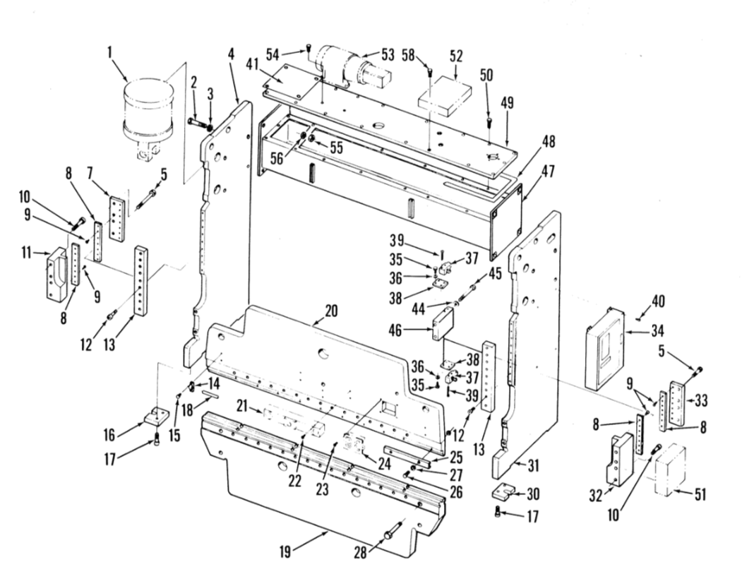
Frame Assembly
| Part # | Part Name |
|---|---|
| 1 | Die Rail |
| 2 | Washer |
| 3 | Die Rail Screw |
| 4 | Die Adjustment Set Screw |
| 5 | Main Motor Control |
| 6 | Frame |
| 7 | Ram |
| 8 | Socket Head Screw |
| 9 | Bearing End Cover |
| 10 | Adjustment Switch Rear Cover |
| 11 | Adjustment Switch Front Cover |
| 12 | Socket Head Cap Screws |
| 13 | Punch Clamping Bar Screws |
| 14 | Punch Clamping Bar |
| 15 | Clamping Bar Locknut |
| 16 | Spring |
| 17 | Gib Screws |
| 18 | Left Gib |
| 19 | Rear Non-Metallic Liner |
| 20 | Front Non-Metallic Liner |
| 21 | Dowel |
| 22 | Lock Nut |
| 23 | Adjusting Screw |
| 24 | Cap Screw |
| 25 | Pivot Adjusting Block |
| 26 | Cap Screw |
| 27 | Pivot Block Cover |
| 28 | Pivot Block |
| 29 | Pivot Shoes |
| 30 | Right Gib |
| 31* | Ram Adjustment Switch |
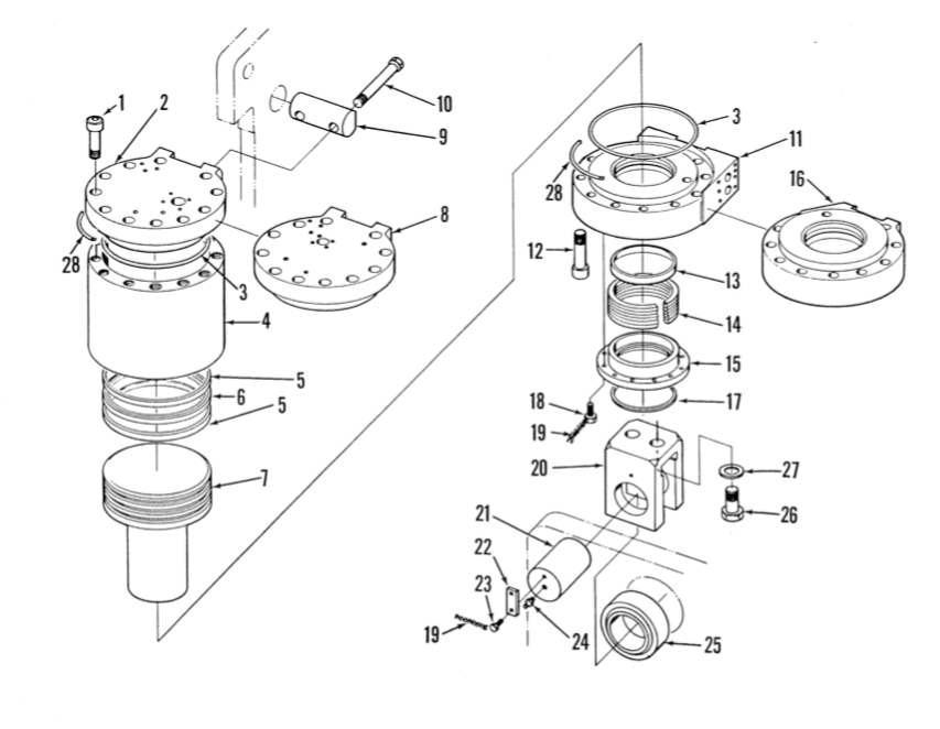
Cylinder Assembly
| Part # | Part Name |
|---|---|
| 1 | Bronze Bushing |
| 2 | Eccentric Cams |
| 3 | Eccentric Cam Keys |
| 4 | Split Flanged Bronze Bushing |
| 5 | Eccentric Shaft |
| 6 | Gear Reducer Key |
| 7 | Split Bronze Bushing |
| 8 | Dowel |
| 9 | Flanged Bronze Bushing |
| 10 | Bearing Caps |
| 11 | Socket Head Cap Screws |
| 12 | Ram Adjusting Motor |
| 13 | Motor Shaft Key |
| 14 | Connection Bushing |
| 15 | Left Connection |
| 16 | Right Connection |
| 17 | Bronze Bushing |
| 17A | Bronze Bushing |
| 18 | Thrust Bearings |
| 19 | Worm |
| 20 | Worm Key |
| 21 | Sprocket Key |
| 22 | Roll Pin |
| 23 | Bearing Retainer |
| 24 | Retainer Set Screw |
| 25 | Snap Ring |
| 26 | Right Adjusting Shaft |
| 27 | Stop Plate Screws |
| 28 | Stop Plate |
| 29 | Adjusting Nut |
| 30 | Connection Cover |
| 31 | Socket Head Capscrews |
| 32 | Ball Cover Right Hand |
| 32A | Left Hand Ball Cover |
| 33 | Shims |
| 34 | Ball Screw |
| 35 | Ball Seat |
| 36 | Ball Pin |
| 37 | Sprocket Box |
| 38 | Large Sprocket |
| 39 | Motor Screw |
| 40 | Box Cover |
| 41 | Sprocket Box Mounting Screws |
| 42 | Cover Screws |
| 43 | Small Sprocket |
| 44 | Chain |
| 45 | Motor Screw |
| 46 | Worm Key |
| 47 | Roll Pin |
| 48 | Left Adjusting Shaft |
| 49 | Bearing Retainer |
| 50 | Roll Pin |
| 51 | Gear Box |
| 52 | Shaft Gear |
| 53 | Gear Box Mounting Screw |
| 54 | Idler Gear |
| 55 | Gear Box Cover |
| 56 | Counter |
| 57 | Idler Shaft |
| 58 | Counter Gear |
| 59 | Cover Screw |
| 60 | Roll Pin |
| 61 | Roll Pin |
| 62 | Set Screw |
| 63 | Coupling Gear |
| 64 | Adjusting Sleeve |
| 65 | Spring |
| 66 | Sleeve Stop |
| 67 | Inner Worm Shaft |
| 68 | Counter Screws |
| 69 | Counter Gear Bushing |
| 70 | Adjusting Shaft Connection Tube |
| 71 | Roll Pins |
| 72 | Spacer |
Stroke & Speed Control
| Part # | Part Name |
|---|---|
| 1 | Socket Head Screw |
| 2 | Right Hand Bearing Cap |
| 3 | Flywheel Bearings |
| 4 | Flywheel |
| 5 | Main Gear Bearings |
| 6 | Left Hand Bearing Cap |
| 7 | Locknut |
| 8 | Set Screw |
| 9 | Main Gear and Output Hub |
| 10 | Intermediate Shaft Bearings |
| 11 | Snap Ring |
| 12 | Intermediate Gear |
| 13 | Intermediate Pinion and Shaft |
| 14 | Keys |
| 15 | Right Hand Drive Shaft Bearing |
| 16 | Driveshaft |
| 17 | Left Hand Drive Shaft Bearing |
| 18 | Countersunk Screws |
| 19 | Sockethead Screws |
| 20 | Oil Fill Plug |
| 21 | Gear Box Housing |
| 22 | Gear Box Cover |
| 23 | Oil Level Window |
| 24 | Main Bearing Cap |
| 25 | Oil Drain Plug |
| 26 | Removable Set Screw to pull #24 |
| 27 | Bearing Cover |
| 28 | Socket Head Screw |
Ram Level Control
| Part # | Part Name |
|---|---|
| 1 | Shafter Collar |
| 2 | Adjusting Ring |
| 3 | Hub |
| 4 | Drive Disc Assembly |
| 5 | Driving Plate |
| 6 | Adjusting Nut |
| 7 | Hex Head Capscrew |
| 8 | Spring |
| 9 | Push Ring |
| 10 | Roll Pin |
| 11 | Spring |
| 12 | Release Latch |
| 13 | Pin (9 Req.) |
| 14 | Snap Ring (18 Req.) |
| 15 | Toggle (6 Req.) |
| 16 | Pin (3 Req.) |
| 17 | Toggle Lever (3 Req.) |
| 18 | Drawrod (See pg. 24) |
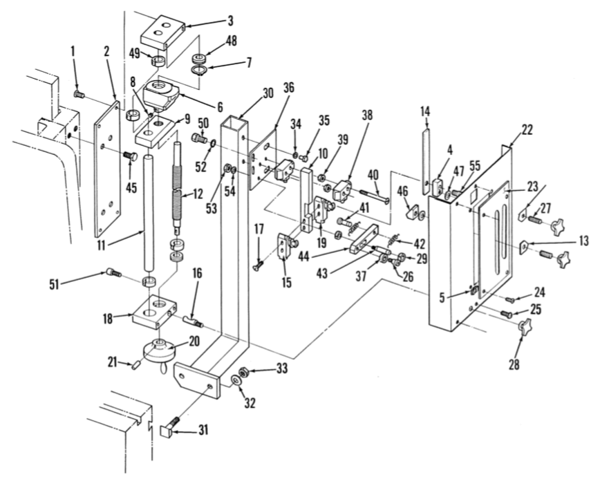
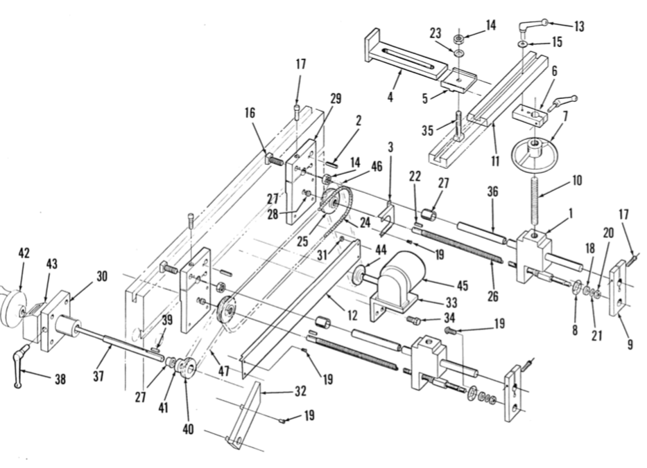
Front Operated, Parallel Adjusted Back Gage
| Part # | Part Name |
|---|---|
| 20 | Belt Guard |
| 21 | Motor Plate |
| 28 | Motor |
| 30 | Support Plate Cap |
| 31 | Left Hand Support Plate |
| 32 | Pivot Pin |
| 33 | Right Hand Support Plate |
| 34 | Snap Ring |
| 35 | Belts |
| 36 | Adjusting Block |
| 37 | Locknut |
| 38 | Adjusting Screw |
| 39 | Sheave |
| 40 | Adjusting Block Screws |
| 41 | Socket Head Screw |
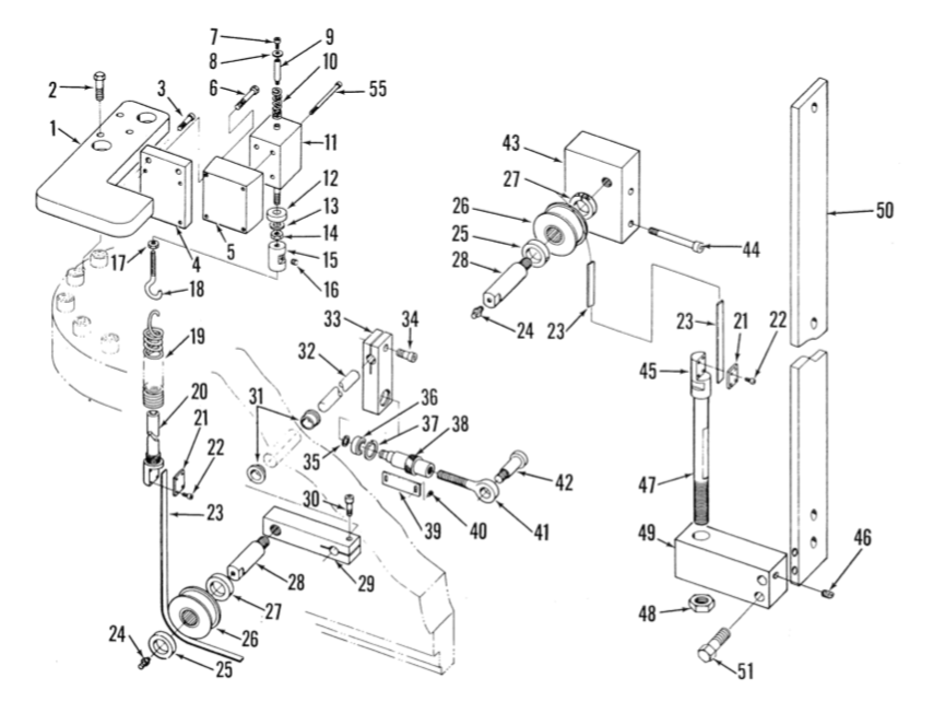
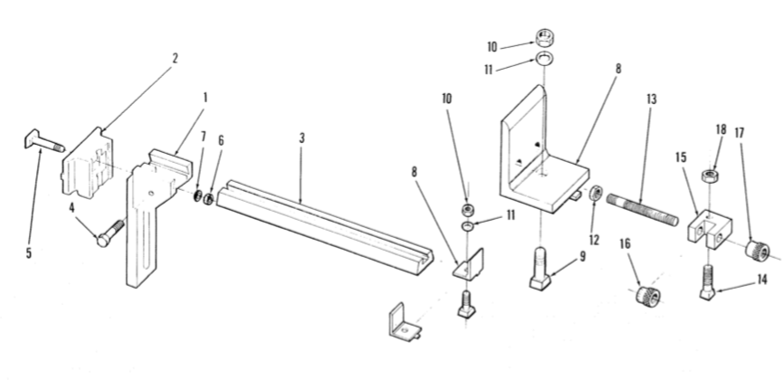
Heavy Duty, Universal Gage Bracket & Gaging Stop
| Part # | Part Name |
|---|---|
| 6 | Belt |
| 13 | Handwheel |
| 14 | Roll Pin |
| 15 | Adjusting Shaft Bearing |
| 17 | Adjusting Shaft |
| 20 | Belt Guard |
| 21 | Motor Plate |
| 22 | Locknuts |
| 23 | Adjusting Screw Locknuts |
| 24 | Motor Plate Pivot Screw |
| 25 | Motor Plate Pivot |
| 26 | Washer |
| 27 | Adjusting Screw Locknuts |
| 28 | Motor and Adjustable Sheave |
| 30 | Support Plate Cap |
| 31 | Left Hand Support Plate |
| 32 | Pivot Pin |
| 33 | Right Hand Support Plate |
| 34 | Snap Ring |
| 41 | Socket Head Screws |
| 42 | Pulley |
