NO 31 & 33 Ring and Circle Shear Form P-15-B
1. Click a link to view parts below or download a PDF Spec Sheet
2. Once you’ve found your part number and part name, request a parts quote
Preguntas? Inicie un chat
Jump to Assembly Parts and Manual Drawings
Click to enlarge
Download a PDF Spec Sheet
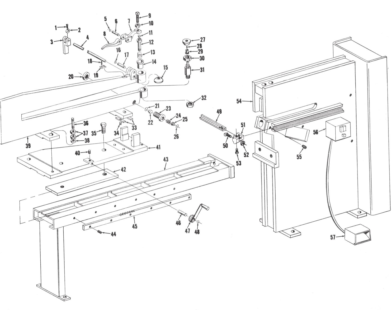
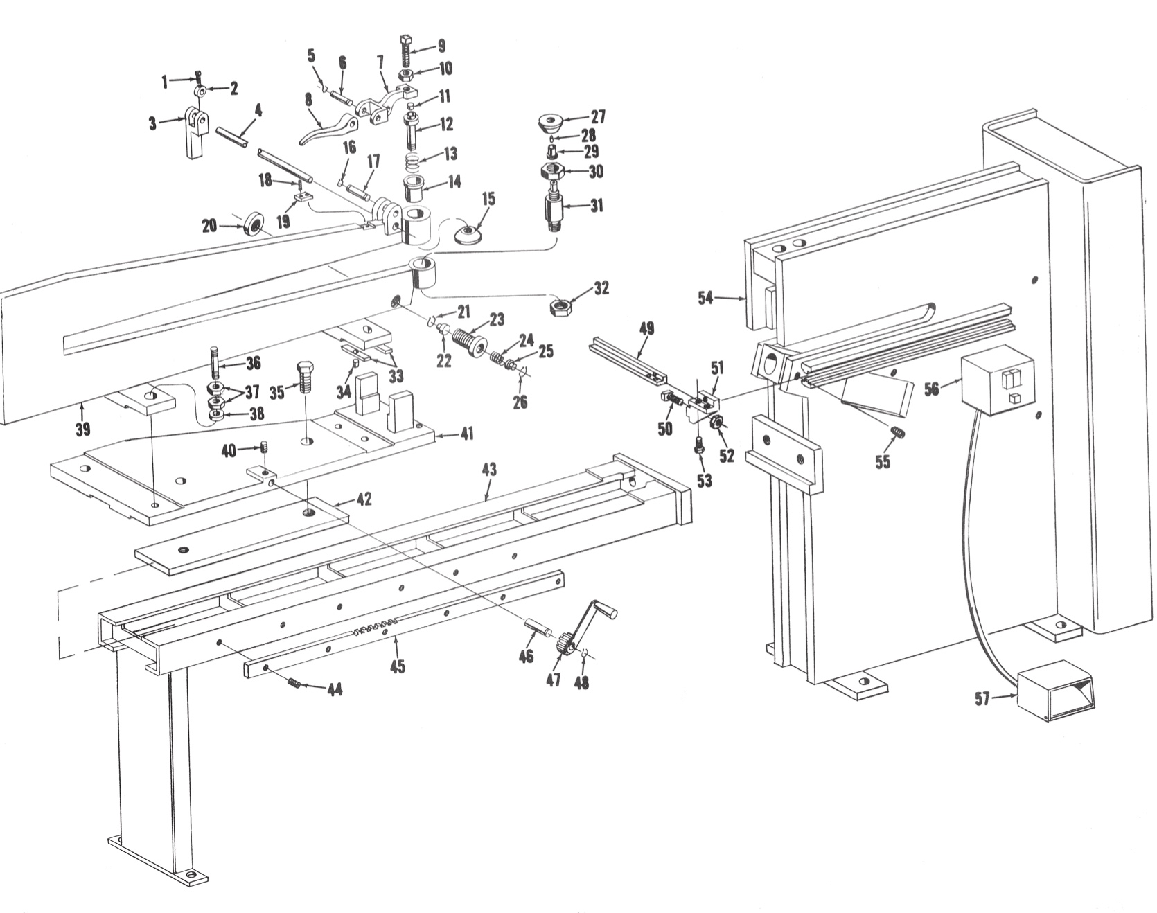
Frame Assembly
| Part # | Part Name |
|---|---|
| 1 | Square Head Set Screw |
| 2 | Collar |
| 3 | Side Gage |
| 4 | Shaft |
| 5 | Snap Ring |
| 6 | Pin |
| 7 | Lever |
| 8 | Handle |
| 9 | Square Head Set Screw |
| 10 | Lock Nut |
| 11 | Wearing Pin |
| 12 | Pin for Upper Disc |
| 13 | Spring |
| 14 | Upper Cartridge |
| 15 | Clamping Disc |
| 16 | Snap Ring |
| 17 | Pin |
| 18 | Set Screw |
| 19 | Pad |
| 20 | Nut |
| 21 | Snap Ring |
| 22 | Piston |
| 23 | Suppressor Sleeve |
| 24 | Spring |
| 25 | Piston |
| 26 | Snap Ring |
| 27 | Clamping Disc |
| 28 | Center Point |
| 29 | Bushing |
| 30 | Nut |
| 31 | Pin for Lower Disc |
| 32 | Nut |
| 33 | Formica Pad |
| 34 | Dowel |
| 35 | Hex Head Cap Screw |
| 36 | Stud |
| 37 | Jam Nut |
| 38 | Washer |
| 39 | Circle Arm |
| 40 | Set Screw |
| 41 | Slide |
| 42 | Plate |
| 43 | Bed |
| 44 | Socket Head Cap Screw |
| 45 | Gear Rack |
| 46 | Crank Pin |
| 47 | Slide Gear and Handle |
| 48 | Snap Ring |
| 49 | Gage |
| 50 | Gage Bolt |
| 51 | Gage Bracket |
| 52 | Nut |
| 53 | Hex Head Cap Screw |
| 54 | Frame |
| 55 | Screw Key |
| 56 | Magnetic Starter |
| 57 | Foot Switch |
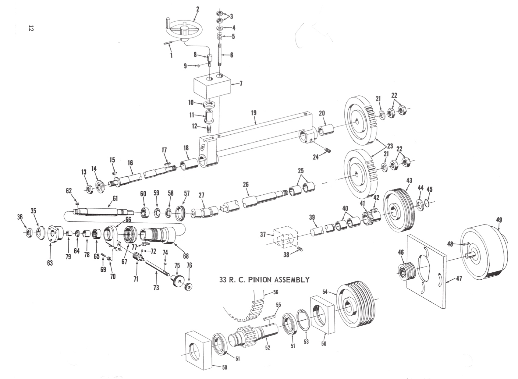
Drive Assembly
| Part # | Part Name |
|---|---|
| 1 | Roll Pin |
| 2 | Revolving Handle |
| 3 | Jam Nuts |
| 4 | Washer |
| 5 | Spring |
| 6 | Stud |
| 7 | Frame |
| 8 | Pin |
| 9 | Woodruff Key |
| 10 | Thrust Bearing |
| 11 | Elevation Nut |
| 12 | Screw |
| 13 | Jam Nut |
| 14 | Upper Cutter |
| 15 | Key |
| 16 | Upper Shaft |
| 17 | Key |
| 18 | Bushing |
| 19 | Rocking Box |
| 20 | Bushing |
| 21 | Washer |
| 22 | Jam Nut |
| 23 | Main Gear |
| 24 | Pivot Screw |
| 25 | Bushing |
| 26 | Lower Shaft |
| 27 | Universal |
| 35 | Lower Cutter |
| 36 | Jam Nut |
| 37 | Frame Member ** |
| 38 | Set Screw ** |
| 39 | Pinion Shaft ** |
| 40 | Bushing ** |
| 41 | Pinion Gear ** |
| 42 | Key ** |
| 43 | Driven Sheave ** |
| 44 | Washer |
| 45 | Snap Ring |
| 46 | Motor Sheave |
| 47 | Motor Plate |
| 48 | Key |
| 49 | Motor |
| 50 | Frame Member * |
| 51 | Bearing * |
| 52 | Pinion Shaft * |
| 53 | Snap Ring * |
| 54 | Driven Sheave * |
| 55 | Key * |
| 56 | Main Gear * |
| 57 | Retainer |
| 58 | Locknut |
| 59 | Washer |
| 60 | Bearing |
| 61 | Inclined Shaft |
| 62 | Key |
| 63 | Outer Bearing Cartridge |
| 64 | Wiper |
| 65 | Bearing |
| 66 | Worm Bracket |
| 67 | Worm Gear |
| 68 | Quill |
| 69 | Stud |
| 70 | Jam Nut |
| 71 | Worm |
| 72 | Roll Pin |
| 73 | Worm Shaft |
| 74 | Key |
| 75 | Adjusting Knob |
| 76 | Clamp Nut |
| 77 | Key |
| 78 | Race |
| 79 | Bearing Sleeve |
| * 33 R.C. Pinion Assembly only | ** 31 R.C. Pinion Assembly only |
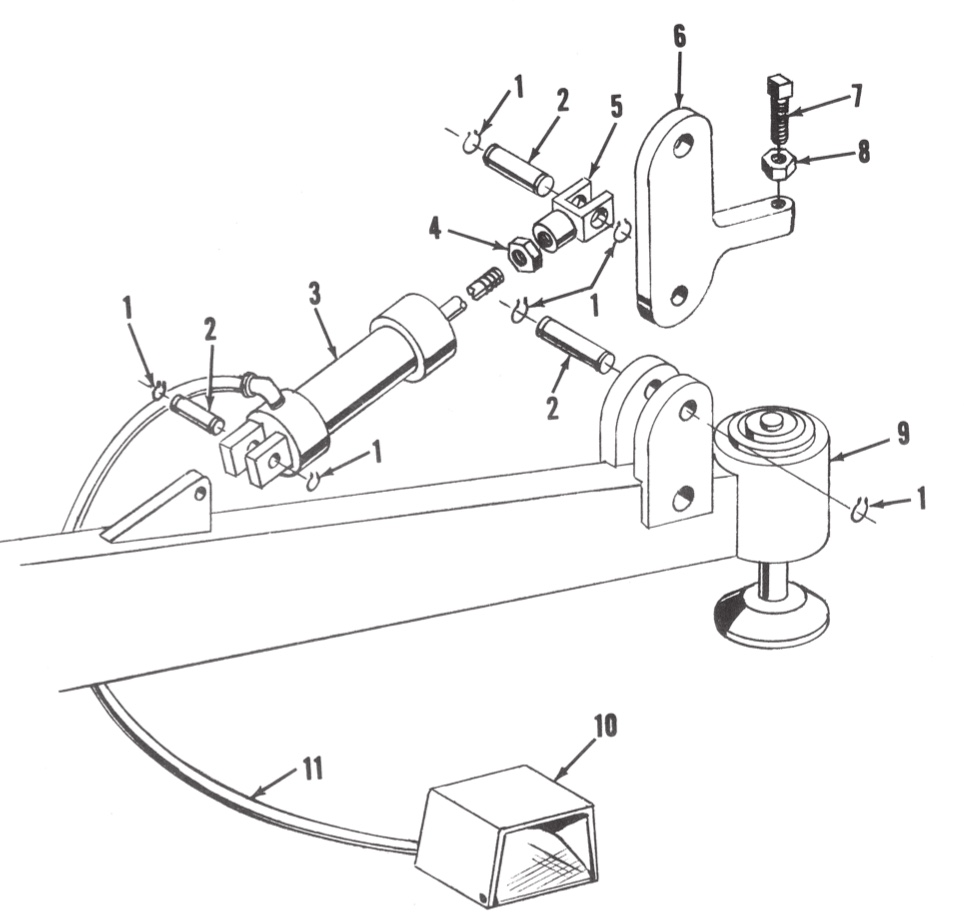
Air Operated Clamping Discs
| Part # | Part Name |
|---|---|
| 1 | Snap Ring |
| 2 | Pin |
| 3 | Air Cylinder |
| 4 | Lock Nut |
| 5 | Clevis |
| 6 | Lever |
| 7 | Square Head Set Screw |
| 8 | Nut |
| 9 | Circle Arm |
| 10 | Foot Air Valve |
| 11 | Hose |
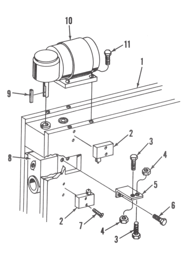
Power Downfeed
| Part # | Part Name |
|---|---|
| 1 | Frame |
| 2 | Limit Switch |
| 3 | Hex Head Cap Screw |
| 4 | Jam Nut |
| 5 | Mounting Plate |
| 6 | Hex Head Cap Screw |
| 7 | Screw |
| 8 | Rocking Box |
| 9 | Key |
| 10 | Motor |
| 11 | Hex Head Cap Screw |
