A-110-3 Bliss Inclinable Presses
1. Click a link to view parts below or download a PDF Spec Sheet
2. Once you’ve found your part number and part name, request a parts quote
Questions? Contact Us
Jump to Assembly Parts and Manual Drawings
Click to enlarge
Download a PDF Spec Sheet
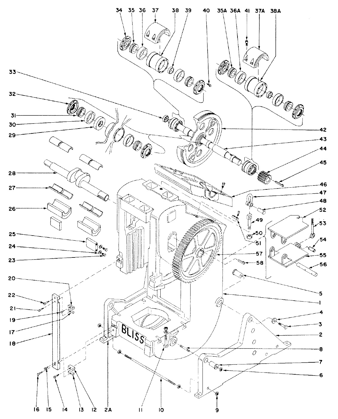
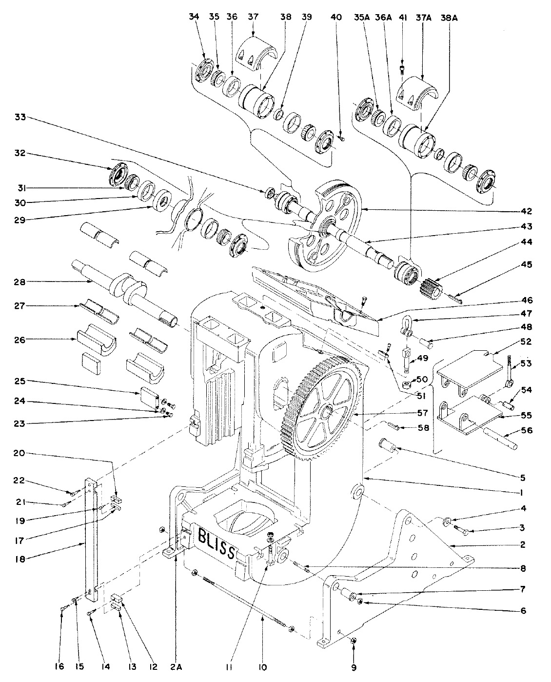
Body Assembly
| Part # | Part Name |
|---|---|
| 1 | Frame |
| 2 | Leg (right hand) |
| 2A | Leg (left hand) |
| 3 | Bolt |
| 4 | Washer |
| 5 | Leg bolt |
| 6 | Hex nut |
| 7 | Fulcrum pin |
| 8 | Stud |
| 9 | Hex nut |
| 10 | Leg tie rod |
| 11 | Bolster bolt |
| 12 | Lower frame key |
| 13 | Tie rod key (lower) |
| 14 | Allen hd. cap screw |
| 15 | Allen hd. cap screw |
| 16 | Allen hd. cap screw |
| 17 | Tie rod key (upper) |
| 18 | Body tie rod |
| 19 | Allen hd. cap screw |
| 20 | Upper frame key |
| 21 | Allen hd. cap screw |
| 22 | Allen hd. cap screw |
| 23 | Hex hd. cap screws (for wedge) |
| 24 | Wedge washer |
| 25 | Wedge |
| 26 | Body box |
| 27 | Main bearing bushing |
| 28 | Crankshaft |
| 29 | Flywheel cone spacer |
| 30 | Bearing cup (flywheel) |
| 31 | Bearing cone (flywheel) |
| 32 | Bearing collar (flywheel) |
| 33 | Cover plate (drive shaft) |
| 34 | Sleeve collar (drive shaft) |
| 35 | Bearing cone (drive shaft, left end) |
| 35A | Bearing cone (drive shaft, right end) |
| 36 | Bearing cup (drive shaft, left end) |
| 36A | Bearing cup (drive shaft, right end) |
| 37 | Driveshaft bearing cap (left end) |
| 37A | Driveshaft bearing cap (right end) |
| 38 | Roller bearing sleeve (left end) |
| 38A | Roller bearing sleeve (right end) |
| 39 | Driveshaft bearing spacer |
| 40 | Hex hd. cap screw |
| 41 | Socket hd. cap screw |
| 42 | Flywheel |
| 43 | Drive shaft |
| 44 | Main pinion |
| 45 | Gib hd. Key |
| 46 | Back bracket |
| 47 | Anchor shackle |
| 48 | Shackle pin |
| 49 | Shackle bolt |
| 50 | Shackle bolt nut |
| 51 | Back bracket key |
| 52 | Motor table |
| 53 | Motor table adj. screw |
| 54 | Adj. screw pin (motor table) |
| 55 | Motor table hinge bracket |
| 56 | Hinge shaft |
| 57 | Main gear |
| 58 | Gib hd. key |
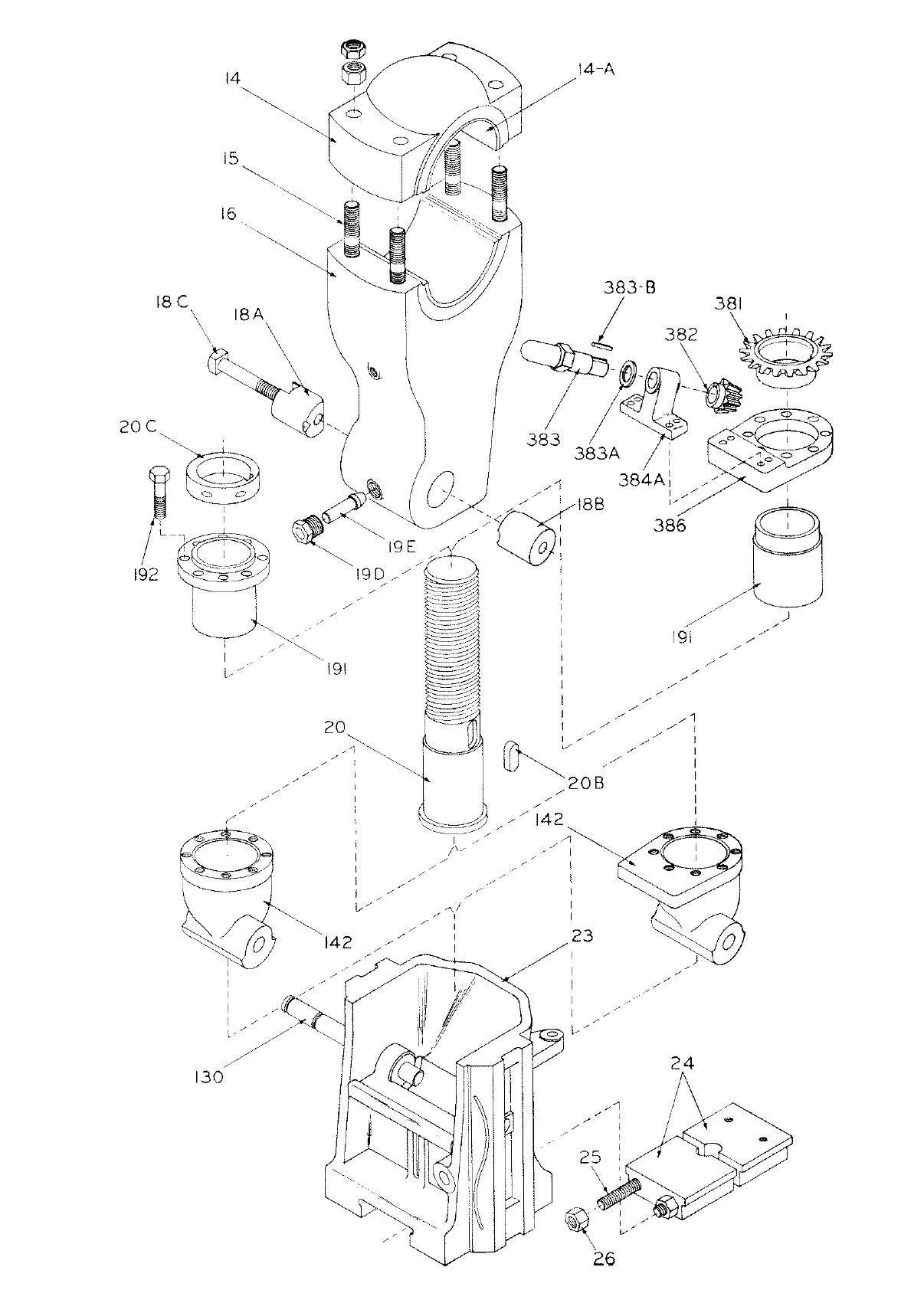
Manual Slide Adjustment
| Part # | Part Name |
|---|---|
| 14 | Connection cap |
| 14A | Connection cap bushing |
| 15 | Connection cap stud |
| 16 | Connection |
| 18A | Connection screw clamping plug (head end) |
| 18B | Connection screw clamping plug (nut end) |
| 18C | Connection screw clamping plug screw |
| 19D | Connection screw clamping plug dummy screw |
| 19E | Connection screw clamping plug spreader |
| 20 | Connection screw |
| 20B | Connection screw gear key |
| 20C | Connection screw adjusting collar |
| 23 | Slide |
| 24 | Punch holder |
| 25 | Punch holder stud |
| 26 | Punch holder stud nut |
| 130 | Connection wrist pin |
| 142 | Connection wrist |
| 191 | Connection screw and wrist retaining bushing |
| 192 | Cap screw |
| 381 | Connection screw gear, bevel |
| 382 | Connection screw gear, pinion bevel |
| 383 | Connection screw hand ratchet |
| 383A | Connection screw hand ratchet washer |
| 383B | Key |
| 384A | Connection screw pinion and shaft bracket |
| 386 | Connection wrist plate |
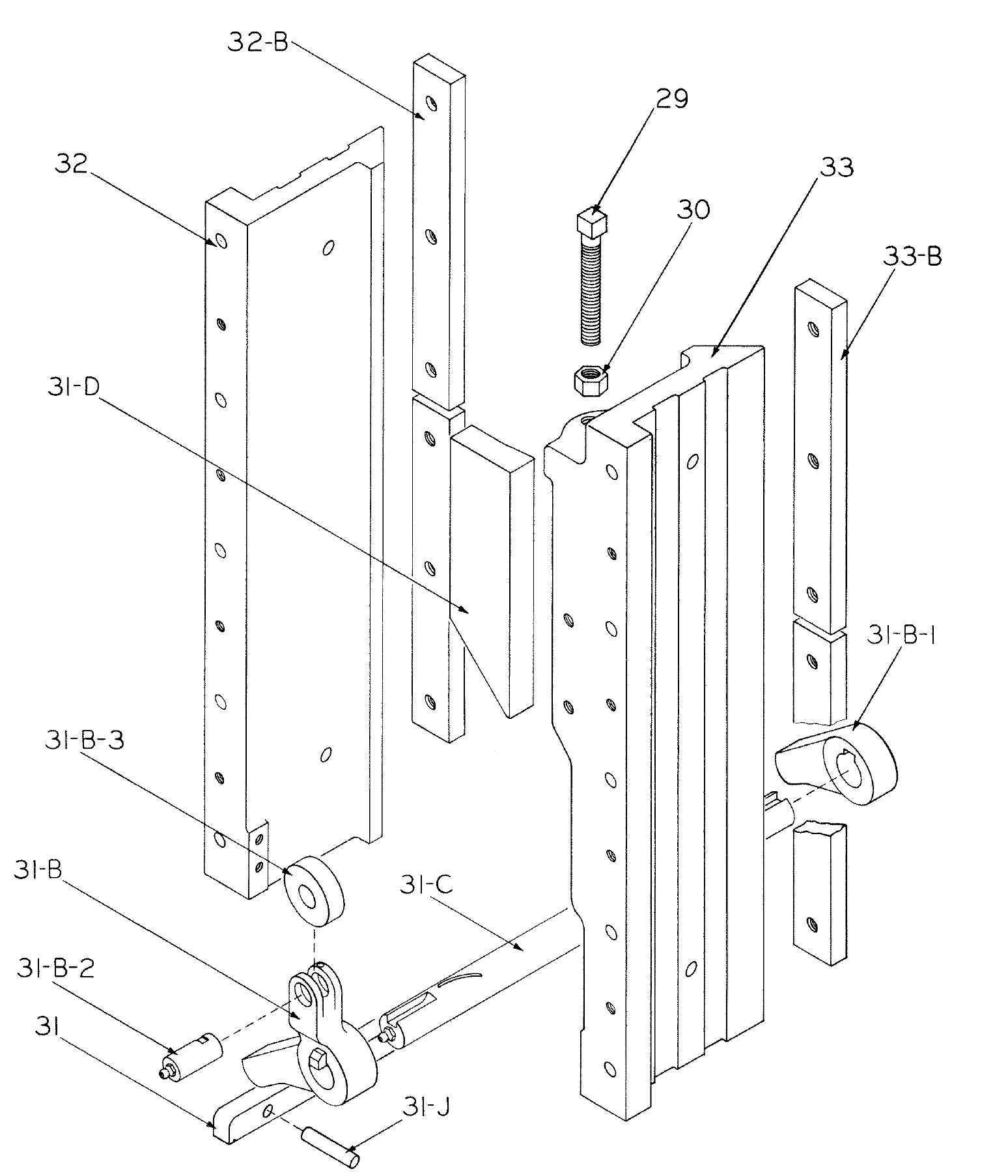
Gibs & Knockout Assembly
| Part # | Part Name | Part # | Part Name |
|---|---|---|---|
| 29 | Cam adjusting screw | 31-C | Knockout lever shaft |
| 30 | Cam adjusting screw nut | 31-D | Knockout cam |
| 31 | Knockout bar | 31-J | Knockout bar retaining pin |
| 31-B | Front knockout lever | 32 | L.H. main gib |
| 31-B-1 | Rear knockout lever | 32-B | L.H. wear strip |
| 31-B-2 | Knockout lever roller pin | 33 | R.H. main gib |
| 31-B-3 | Knockout roller | 33-B | R.H. wear strip |


