FM Series
1. Click a link to view parts below or download a PDF Spec Sheet
2. Once you’ve found your part number and part name, request a parts quote
Questions? Contact Us
Jump to Assembly Parts and Manual Drawings
Click to enlarge
Download a PDF Spec Sheet
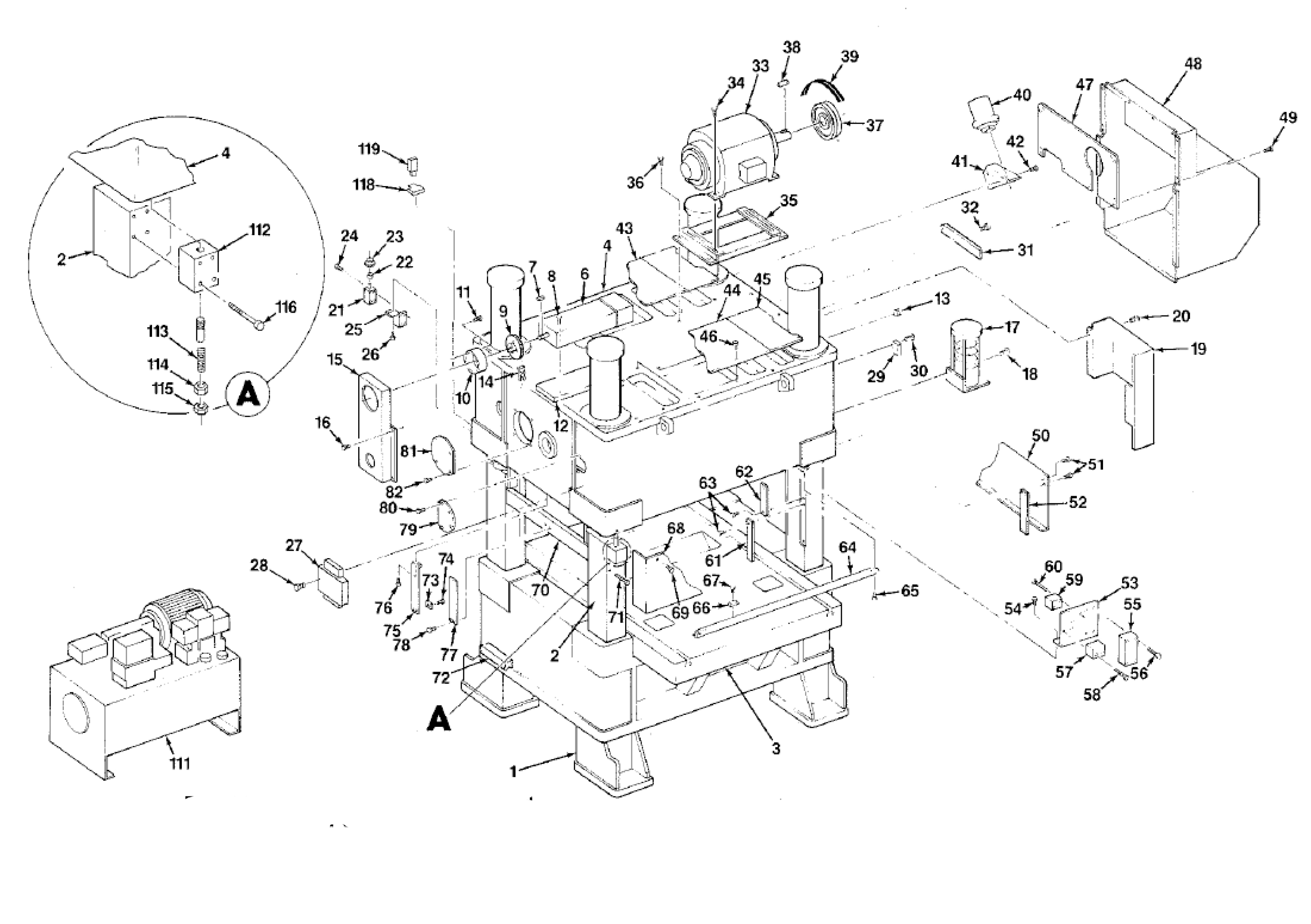
Frame
Four shipping brackets (no.112) are provided to hold crown and columns together when lifting machine.
Remove these brackets before operating machine.
Save and re-install all four brackets when lifting machine in the future.
Torque 3/4″ socket head capscrews (no.116) to 370 ft. lbs.
Torque 1 3/4″ hex nuts (no.114) to 675 lbs.
| Part # | Part Name |
|---|---|
| 1 | Bed |
| 2 | Column and Cylinder Assembly (see separate part list) |
| 3 | Bolster |
| 4 | Crown |
| 5 | Drive Assembly (not shown; see separate part list) |
| 6 | Limit Switch |
| 7 | Key |
| 8 | Limit Switch Mounting Screw |
| 9 | Limit Switch Sprocket |
| 10 | Stroke Indicator Dial |
| 11 | Dial Mounting Screw |
| 12 | Limit Switch Bracket |
| 13 | Plug for Gear Case Level |
| 14 | Chain |
| 15 | Limit Switch Chain Guard |
| 16 | Guard Mounting Screw |
| 17 | Lubrication Pump |
| 18 | Pump Mounting Screw |
| 19 | Lubrication Pump Cover |
| 20 | Screw for Cover |
| 21 | Counter |
| 22 | Bushing |
| 23 | Counter Sprocket |
| 24 | Counter Mounting Screw |
| 25 | Counter Bracket |
| 26 | Counter Bracket Screw |
| 27 | Clutch And Brake Solenoid |
| 28 | Screw |
| 29 | Flywheel Brake Pressure Switch |
| 30 | Screw |
| 31 | Spacer for Back Plate |
| 32 | Spacer Screw |
| 33 | Motor |
| 34 | Motor Mounting Screw |
| 35 | Motor Base |
| 36 | Base Mounting Screw |
| 37 | Motor Sheave |
| 38 | Key |
| 39 | V Belts |
| 40 | Flywheel Brake (see pg. 14) |
| 41 | Flywheel Brake Bracket |
| 42 | Brake Bracket Screw |
| 43 | Rear Crown Cover |
| 44 | Front Crown Cover |
| 45 | Right Front Crown Cover |
| 46 | Crown Cover Screw |
| 47 | Belt Guard Back Plate |
| 48 | Belt Guard |
| 49 | Belt Guard Mounting Screw |
| 50 | R.H. or L.H. Chain Guard |
| 51 | Chain Guard Mounting Screw |
| 52 | Chain Guard Back Plate |
| 53 | Hudraguard Mounting Bracket |
| 54 | Bracket Mounting Screw |
| 55 | Hydraguard Valve |
| 56 | Screw |
| 57 | Hydraguard Solenoid Valve |
| 58 | Screw |
| 59 | Hydraguard Pressure Switch |
| 60 | Screw |
| 61 | Lower Gib |
| 62 | Upper Gib |
| 63 | Gib Mounting Screw |
| 64 | Chain Support |
| 65 | Chain Support Screw |
| 66 | Chain Guide |
| 67 | Guide Mounting Screw |
| 68 | Front or Rear Chain Guard |
| 69 | Chain Guard Mounting Screw |
| 70 | Column Tie Bar and Shims |
| 71 | Tie Bar Mounting Screw |
| 72 | Die Block |
| 73 | "Crown Up" Switch |
| 74 | Screw |
| 75 | Crown Switch Bracket |
| 76 | Bracket Screw |
| 77 | Frame Switch Bracket |
| 78 | Bracket Screw |
| 79 | Crown End Cover |
| 80 | Cover Screw |
| 81 | Crown Cover |
| 82 | Cover Screw |
| 111 | Hydraulic Pump and Reservoir Unit |
| 112 | Shipping Bracket |
| 113 | Tie Rod |
| 114 | Hex Nut |
| 115 | Jam Nut |
| 116 | Screw |
| 118 | Crown Switch Plate |
| 119 | "Crown Down" Switch |
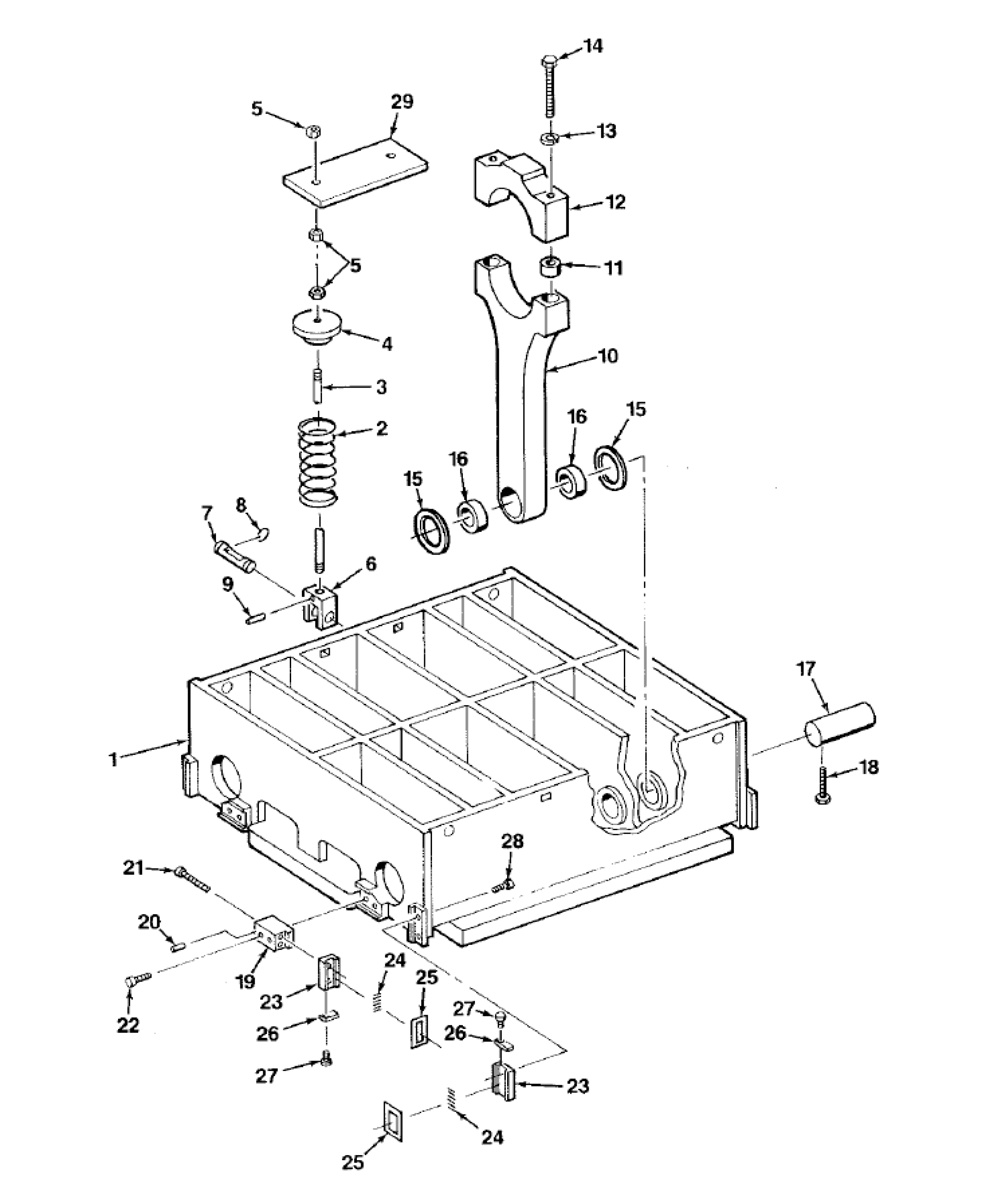
| Part # | Part Name |
|---|---|
| 1 | Slide |
| 2 | Counter Balance Spring |
| 3 | Piston Rod |
| 4 | Spring Retainer Cap |
| 5 | Hex Nut |
| 6 | Clevis |
| 7 | Clevis Pin |
| 8 | Retaining Ring |
| 9 | Roll Pin |
| 10 | Connection |
| 11 | Locating Bushing |
| 12 | Connection Cap |
| 13 | Lock Washer |
| 14 | Screw |
| 15 | Thrust Washer |
| 16 | Bearing |
| 17 | Wrist Pin |
| 18 | Screw |
| 19 | Gib Bearing Housing Bracket |
| 20 | Dowel |
| 21 | Screw |
| 22 | Screw |
| 23 | Gib Bearing Housing |
| 24 | Needle Rollers |
| 25 | Bearing Retainer Plate |
| 26 | Bearing Housing Cap |
| 27 | Screw |
| 28 | Screw |
| 29 | Spring Retainer |
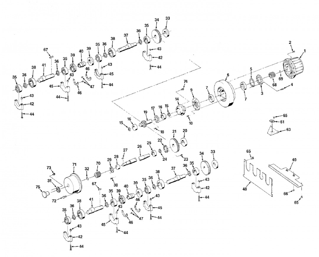
Drive Assembly
| Part # | Part Name |
|---|---|
| 1 | Clutch (See pg. 10) |
| 2 | Clutch Mounting Screw |
| 3 | Flywheel Bearing Cover |
| 4 | Screw for Cover |
| 5 | Retaining Ring |
| 6 | Flywheel |
| 7 | Bearing |
| 9 | Flywheel Bearing Cover |
| 10 | Cover Mounting Screw |
| 14 | Quill |
| 15 | Retaining Ring |
| 16 | Bearing |
| 17 | Bearing Retainer |
| 18 | Retainer Screw |
| 19 | Drive Shaft |
| 20 | Shrink Disc |
| 21 | Idler Gear |
| 22 | Bearing Retainer |
| 23 | Retainer Screw |
| 24 | Retaining Ring |
| 25 | Bearing |
| 26 | Idler Shaft |
| 27 | Key |
| 28 | Bearing |
| 29 | Bearing Retainer |
| 30 | Retainer Screw |
| 31 | Sprocket |
| 32 | Retaining Ring |
| 33 | Shrink Disc |
| 34 | Eccentric Gear |
| 35 | Bearing |
| 36 | Retaining Ring |
| 37 | R.H. Eccentric Shaft |
| 38 | Connection Bearing |
| 39 | Shrink Disc |
| 40 | Shaft Coupling |
| 41 | L.H. Eccentric Shaft |
| 42 | Outer Bearing Cap |
| 43 | Locating Dowel |
| 44 | Bearing Cap Screw |
| 45 | Inner Bearing Cap |
| 46 | Bearing Retainer |
| 47 | Retainer Screw |
| 48 | Gear Case Side Cover |
| 49 | Gear Case Bottom Cover |
| 61 | Gear Lube Filler Unit |
| 63 | R.H. Front Crown Cover (reference) |
| 65 | Screw |
| 66 | Pipe Plug |
| 67 | Key for Eccentric Shaft |
| 68 | Clutch Driving Hub |
| 69 | Hub Retaining Ring |
| 70 | Brake Driving Hub |
| 71 | Brake (See pg. 12) |
| 72 | Brake Mounting Bolts |
| 73 | Sprocket Mounting Bolts |
| 74 | Quill Mounting Bolts |
| 75 | Disc Hub for Feed |
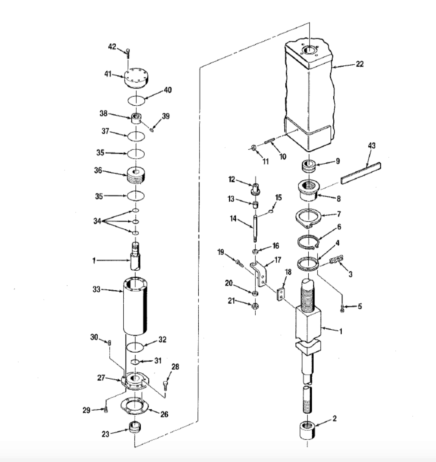
Column and Cylinder Assembly
| Part # | Part Name |
|---|---|
| 1 | Column (specify L.H. or R.H.,front or rear) |
| 2 | Tie Rod Nut |
| 3 | Chain |
| 4 | Adjusting Nut Sprocket |
| 5 | Sprocket Screw |
| 6 | Retaining Ring |
| 7 | Chain Support Bracket |
| 8 | Column Adjusting Nut |
| 9 | Lower Tie Rod Bushing |
| 10 | Set Screw |
| 11 | Hex Nut |
| 12 | Idler Sprocket |
| 13 | Bushing |
| 14 | Idler Sprocket Shaft |
| 15 | Retaining Ring |
| 16 | Washer |
| 17 | Chain Idler Bracket |
| 18 | Idler Bracket Spacer |
| 19 | Bracket Screw |
| 20 | Washer |
| 21 | Nut |
| 22 | Crown (reference) |
| 23 | Upper Tie Rod Bushing |
| 24 | Shim |
| 25 | Cylinder Mounting Plate |
| 26 | Plate Mounting Screw |
| 27 | Cylinder Mounting Screw |
| 28 | Jack Screw |
| 29 | Rod Seal |
| 30 | "O" Ring |
| 31 | Cylinder |
| 32 | "O" Ring with Back-up Rings |
| 33 | Wear Ring |
| 34 | Piston |
| 35 | Piston Seal |
| 36 | Piston Nut |
| 37 | Set Screw |
| 38 | "O"Ring |
| 39 | Cylinder Cover |
| 40 | Cover Screw |
| 41 | Wrench for Column Adjusting Nut |
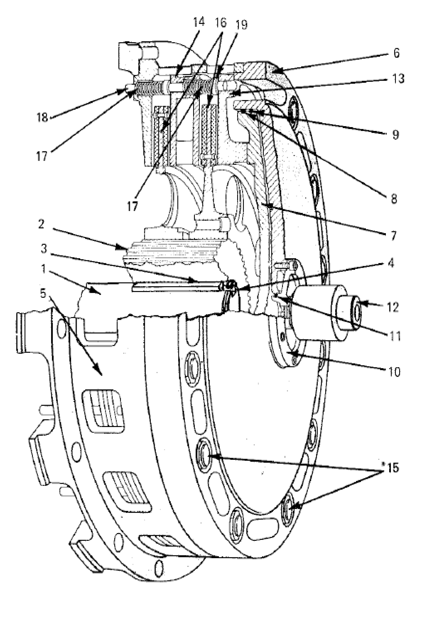
Air Friction Clutch – LI-P
| Part # | Part Name |
|---|---|
| 1 | Drive Shaft |
| 2 | Driving Hub |
| 3 | Key |
| 4 | Retainer Ring |
| 5 | Clutch Housing |
| 6 | Clutch Cylinder |
| 7 | Clutch Piston |
| 8 | Piston Wiper |
| 9 | Piston "O" Ring |
| 10 | Rotary Air Seal Adapter |
| 11 | Adapter "O" Ring |
| 12 | Rotary Air Seal |
| 13 | Pressure Plate |
| 14 | Inner Pressure Plate |
| *15 | Pressure Plate Guides & Nut |
| 16 | Friction Disc |
| 17 | Spreader Spring |
| 18 | Spring Guide |
| 19 | Guide Collar |
*Refer to table below for recommended torque value.
Torque Values
| Torque Values by Friction Disc Diameter | |
|---|---|
| 8" | 25-30 ft/lbs |
| 10" | 30-35 ft/lbs |
| 11" | 35-40 ft/lbs |
| 13" | 45-50 ft/lbs |
| 17" | 70-80 ft/lbs |
| 18" | 70-80 ft/lbs |
| 21" | 90-100 ft/lbs |
| 25" | 110-120 ft/lbs |
| 30" | 190-200 ft/lbs |
| 35" | 220-230 ft/lbs |
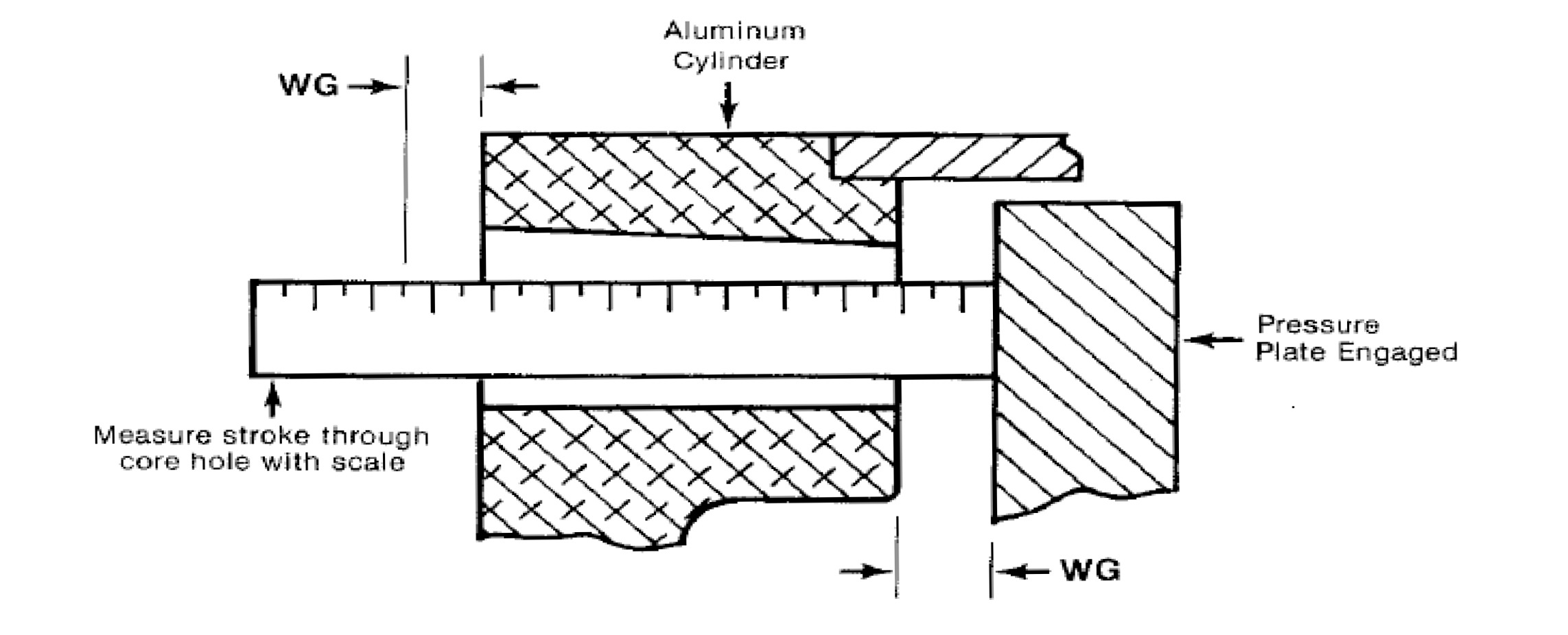
Clutch Lining Replacement
| DISC QTY. | DISC DIA. | WG | DISC QTY. | DISC DIA. | WG | |
|---|---|---|---|---|---|---|
| 1 | 08" | 1/4" | 1 | 18 1/2" | 3/8" | |
| 2 | 08" | 3/8" | 2 | 18 1/2" | 5/8" | |
| 1 | 10" | 1/4" | 1 | 21" | 7/16" | |
| 2 | 10" | 7/16" | 2 | 21" | 7/16" | |
| 1 | 11 1/2" | 1/4" | 3 | 21" | 9/16" | |
| 2 | 11 1/2" | 3/8" | 1 | 25" | 1/2" | |
| 1 | 13 1/2" | 1/4" | 2 | 25" | 9/16" | |
| 2 | 13 1/2" | 7/16" | 1 | 35" | 9/16" | |
| 1 | 17" | 7/16" | 2 | 35" | 5/8" | |
| 2 | 17" | 7/16" | ||||
| DISC RELINE SPECIFICATIONS | ||||||
| Disc Diameter | Thickness New | Thickness for Reline | Disc Diameter | Thickness New | Thickness for Reline | |
| 11 1/2" | .56" | .44" | 21" | 1.38" | 1.25" | |
| 13 1/2" | .56" | .44" | 25" | .97" | .84" | |
| 17" | 1" | .88" | 30" | 1.03" | .90" | |
| 18 1/2" | 1" | .88" | 35" | 1.03" | .90" |
Click to enlarge
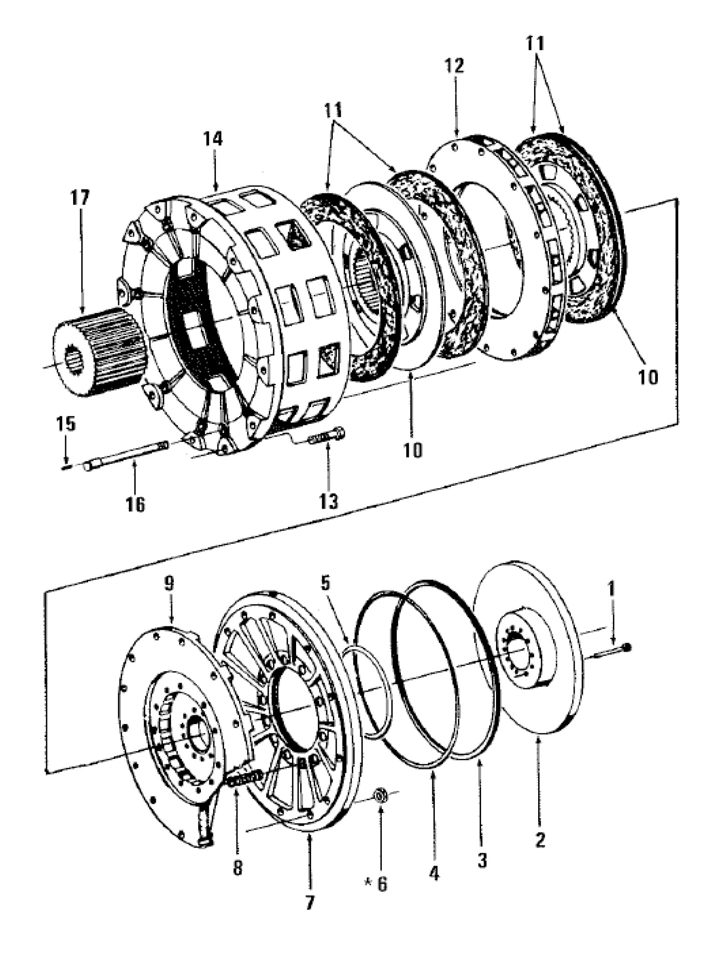
Air Releasing Disc Brake
| Part # | Part Name |
|---|---|
| 1 | Piston Screw (Remove to replace seal and rings.) |
| 2 | Piston |
| 3 | Piston Dust Seal |
| 4 | Piston Ring (outer) |
| 5 | Piston Ring (inner) |
| *6 | Cylinder Stud Nut (Remove to replace linings.) |
| 7 | Cylinder |
| 8 | Spring |
| 9 | Pressure Plate |
| 10 | Brake Disc (quantity may vary) |
| 11 | Brake Lining (quantity may vary) |
| 12 | Center Plate (not used with single disc) |
| 13 | Brake Ring Mounting Screw |
| 14 | Brake Ring |
| 15 | Brake Stud Pin |
| 16 | Brake Stud |
| 17 | Brake Hub |
| 18 | Lining Rivet (not shown) |
*Refer to table below for recommended torque value.
Torque Values
| Torque Values by Friction Disc Diameter | |
|---|---|
| 8" | 25-30 ft/lbs |
| 10" | 30-35 ft/lbs |
| 11" | 35-40 ft/lbs |
| 13" | 45-50 ft/lbs |
| 17" | 70-80 ft/lbs |
| 18" | 70-80 ft/lbs |
| 21" | 90-100 ft/lbs |
| 25" | 110-120 ft/lbs |
| 30" | 190-200 ft/lbs |
| 35" | 220-230 ft/lbs |
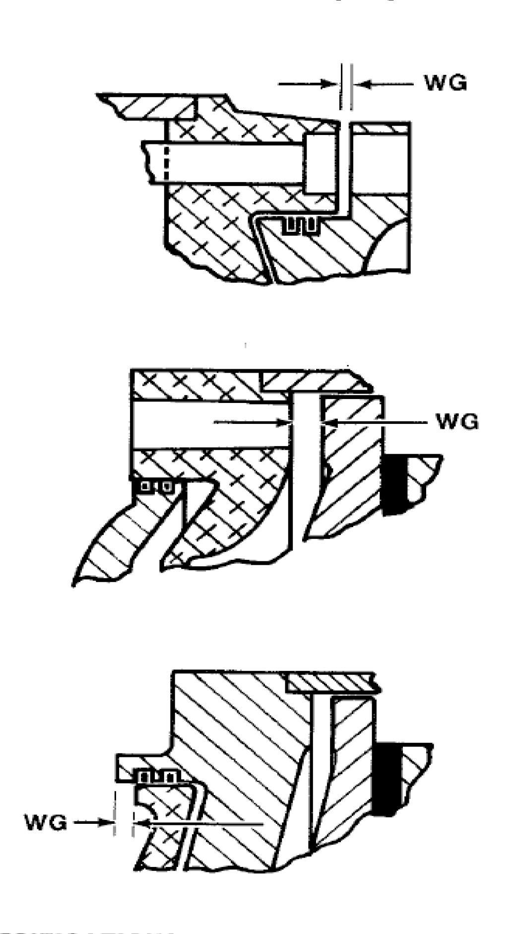
Brake Lining Replacement
Replace linings on Niagara Air Releasing Brakes when the WG reches the WG figure given in the following tables:
| DISC QTY. | DISC DIA. | WG | DISC RELINE SPECIFICATIONS | |||||
|---|---|---|---|---|---|---|---|---|
| DISC QTY. | DISC DIA. | WG | Disc Diameter | Thickness New | Thickness for Reline | Disc Diameter | Thickness New | Thickness for Reline |
| 1 | 08" | 1/8" | 11 1/2" | .56" | .44" | 21" | 1.38" | 1.25" |
| 2 | 08" | 0 | 13 1/2" | .56" | .44" | 25" | .97" | .84" |
| 1 | 35" | 0 | 17" | 1" | .88" | 30" | 1.03" | .90" |
| 2 | 35" | 0 | 18 1/2" | 1" | .88" | 35" | 1.03" | .90" |
| DISC QTY. | DISC DIA. | WG | ||||||
| 1 | 13" | 1/4" | ||||||
| 2 | 13" | 3/8" | ||||||
| 1 | 21" | 7/16" | ||||||
| 2 | 21" | 7/16" | ||||||
| 1 | 25" | 7/16" | ||||||
| 2 | 25" | 7/16" | ||||||
| DISC QTY. | DISC DIA. | WG | ||||||
| 1 | 11" | 5/32" | ||||||
| 2 | 11" | 5/32" | ||||||
| 1 | 17" | 3/32" | ||||||
| 2 | 17" | 3/16" |
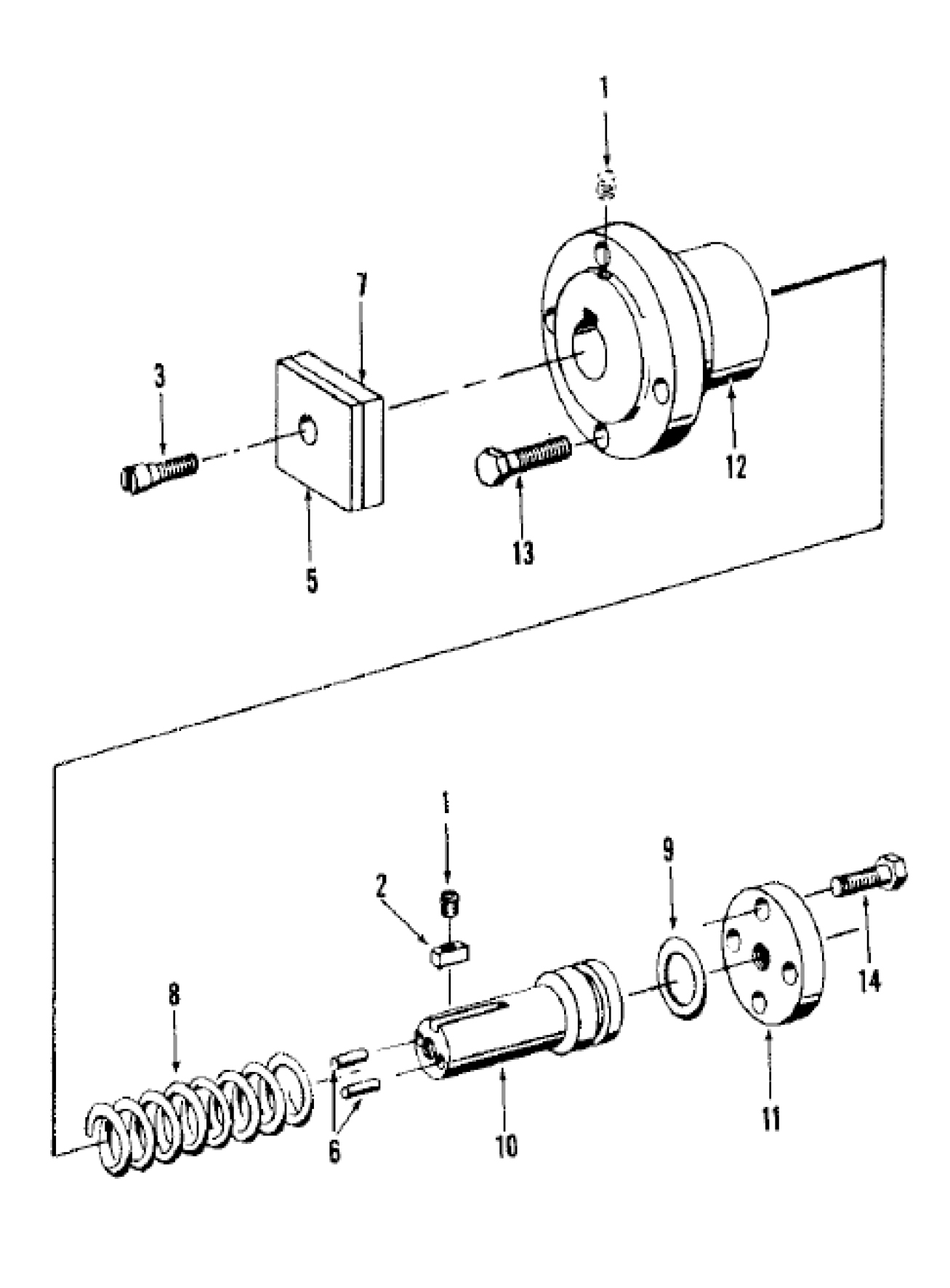
Air Operated Flywheel Brake
| Part # | Part Name |
|---|---|
| 1 | Key Dowel Pin |
| 2 | Guide Key |
| 3 | Mounting Screw |
| 5 | Brake Lining |
| 6 | Dowel Pin |
| 7 | Brake Shoe |
| 8 | Spring |
| 9 | "O" Ring |
| 10 | Piston |
| 11 | Cylinder Cover |
| 12 | Cylinder |
| 13 | Cylinder Mounting Screw |
| 14 | Cover Mounting Screw |

